What Is a Mechanical Flange and How Does It Work?
A Mechanical Flange is a precision-engineered connection used to join pipes, valves, pumps, and other equipment. It usually consists of two flanged faces, a gasket, and several bolts. These parts work together to create a controlled, pressure-resistant joint. The bolts apply clamping force across the connection. That force compresses the gasket against both sealing faces. The gasket then fills small surface imperfections, limiting fluid or gas leakage.
It looks simple.
In practical installations, flange performance depends on more than bolt tightness. Engineers consider pressure, temperature, fluid type, pipe size, flange material, and facing design. ASME and EN standards provide useful guidance, but the correct specification must match the actual service conditions. During maintenance, technicians inspect corrosion, scratches, uneven gaps, damaged threads, and gasket deformation. A torque wrench helps apply measured tightening force, while cross-pattern tightening reduces uneven loading. Small details matter. A single contaminated sealing face can undermine an otherwise carefully prepared joint.
Field experience also reveals an important limitation: a Mechanical Flange does not seal by itself. Poor alignment, unsuitable gasket selection, or repeated thermal cycling can cause failure. Some installations appear secure during a visual check, yet leak after pressure changes. That is why qualified engineers review drawings, material certificates, installation records, and test results. This article explains the main flange components, the sealing mechanism, common connection types, and practical inspection principles. It also questions a common assumption: tighter bolts do not always mean a safer connection. In some cases, excessive force damages the gasket or distorts the flange.
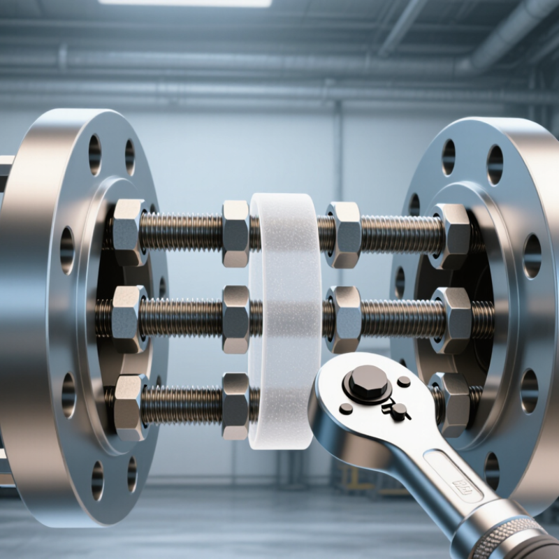
Mechanical Flange Definition and Its Role in Piping Systems
A mechanical flange is a machined ring used to connect pipes, valves, pumps, or other equipment. It usually has bolt holes and a sealing face. During installation, two flange faces meet with a gasket between them. Bolts apply controlled pressure, helping the gasket prevent fluid or gas leakage.
This connection plays an important role in piping systems. It allows technicians to remove equipment without cutting the pipe. It also supports inspection, cleaning, and future maintenance. A reliable flange joint depends on correct alignment, suitable gasket selection, and even bolt tightening. Pressure rating, temperature, pipe material, and fluid type must match the applicable engineering requirements. The idea seems simple. The details are not.
A poorly tightened bolt can create uneven gasket stress. Excessive force may damage the gasket or distort the flange. Field inspections should check corrosion, damaged threads, face scratches, and signs of leakage. Measurements should be recorded, not guessed. One common mistake is treating every flange connection as interchangeable. Dimensions may look similar, while their ratings differ. That assumption deserves careful review.
Tips: Clean both sealing faces before assembly. Check the gasket for cuts or compression damage. Tighten bolts in a cross-pattern, using a verified torque tool. Recheck alignment before applying pressure. Where possible, follow the project specification and the relevant piping code.

Main Components and Structural Features of a Mechanical Flange
What Is a Mechanical Flange and How Does It Work?
A mechanical flange is a shaped connection that joins pipes, shafts, valves, or equipment housings. It transfers pressure, torque, or alignment forces through a controlled interface. In piping systems, two flanges clamp a gasket between their facing surfaces. Bolts create the required preload and help prevent leakage during operation. In rotating equipment, the flange may connect shafts and transmit torque through bolts or fitted surfaces.
The main body is the flange plate, which provides stiffness and supports the connection load. Its central bore matches the pipe or shaft diameter. A raised hub can reinforce the joint and reduce stress around the bore. The flange face may be flat, raised, grooved, or specially machined for a sealing ring. Around the face, evenly spaced bolt holes distribute clamping force. A small detail matters. Uneven spacing can create localized pressure and distortion.
During routine inspections, technicians check bolt condition, face damage, alignment, and gasket compression. A clean surface is essential. Rust, scratches, or trapped debris can form leakage paths. The material must also suit the temperature, pressure, vibration, and surrounding environment. Oversized bolts do not automatically improve reliability. Excessive tightening can deform the flange or crush the gasket. In practice, installation errors remain common, especially when alignment appears acceptable but the bore is slightly offset. That detail deserves a second look.
How Mechanical Flanges Create Secure, Sealed Connections
A mechanical flange joins two sections of pipe, equipment, or ductwork with a bolted connection. Its sealing performance depends on more than metal-to-metal contact. A gasket sits between the flange faces and fills tiny surface irregularities. When bolts apply even pressure, the gasket compresses and blocks the path of fluid, gas, or air. The flange also keeps the connected parts aligned during operation.
The connection starts with careful preparation. Technicians inspect the flange faces for scratches, corrosion, dirt, or distortion. Even a small defect can create a leak channel. The gasket must match the service temperature, pressure, and fluid. It should sit centrally, without folds or unnecessary sealant. Then, bolts are tightened in a crisscross pattern. This method spreads the load across the joint instead of crushing one side.
Torque matters, but it is not the whole story. Bolt condition, lubrication, flange stiffness, and temperature changes can affect clamping force. In field work, a joint may feel tight while carrying uneven pressure. That is easy to miss. A calibrated torque tool and a documented tightening sequence improve reliability. After assembly, operators should check for movement, seepage, and unusual vibration during controlled service. Rechecking may also be necessary after thermal cycling. Small oversights often decide whether a sealed connection lasts for years or needs an early repair.
Common Mechanical Flange Types and Their Applications
A mechanical flange is a machined or formed rim that joins equipment, pipes, or valves. It creates a removable connection without cutting the assembly apart. Bolts clamp two flange faces together, while a gasket fills small surface imperfections. The joint must resist pressure, vibration, heat, and movement. That detail matters.
Common flange types serve different installation needs. Weld-neck flanges suit high-pressure piping because their tapered hubs reduce stress concentration. Slip-on flanges slide over pipes and support faster installation, but they may offer less strength in severe service. Threaded flanges attach to threaded pipe where welding is unsuitable. Blind flanges close pipe ends or equipment openings during testing and maintenance. Socket-weld flanges work well on smaller diameter lines. Lap-joint flanges allow easier alignment and repeated disassembly. Each type has trade-offs.
In water treatment plants, flanges connect pumps, filters, and process lines. HVAC systems use them around chillers, pumps, and large valves. Chemical facilities often require corrosion-resistant materials and carefully selected gaskets. Pressure vessels may use heavy-duty flanges for inspection access. Engineers check pressure ratings, temperature limits, bolt loads, face finish, and material compatibility before installation. Field conditions are often messier than drawings. A flange that fits dimensionally may still fail through poor alignment, uneven tightening, or gasket damage. One practical lesson is clear: installation quality matters as much as flange selection.
What Is a Mechanical Flange and How Does It Work?
A mechanical flange is a bolted connection used to join pipes, valves, pumps, and other equipment. Two flanges compress a gasket between their faces to create a detachable, pressure-tight seal.
The chart shows representative pressure ratings for forged carbon-steel flanges at 100°F (38°C) across common pressure classes. Typical flange types include weld neck flanges for high-stress piping, slip-on flanges for general-purpose systems, socket weld flanges for smaller high-pressure lines, threaded flanges where welding is impractical, blind flanges for line isolation, and lap joint flanges where frequent dismantling is required. Actual allowable pressure depends on material, temperature, size, gasket, bolts, and the applicable piping standard.
Installation, Maintenance, and Safety Considerations
A mechanical flange joins pipes, valves, or equipment through aligned faces and controlled bolt pressure. Installation begins with checking flange size, rating, bolt holes, and gasket type. Never force misaligned pipework into position. That stress can distort the joint before tightening starts. Clean both sealing faces with a suitable tool, not a sharp object that creates scratches. Place the gasket centrally, then tighten bolts gradually in a diagonal pattern. Use a calibrated torque wrench and follow the equipment specification.
Small details matter. Bolts should be clean, undamaged, and properly lubricated only when approved. Uneven tightening can produce a hidden leak path. I have seen joints that looked secure but loosened after thermal cycling. A pressure test should follow installation, with people kept outside the potential release area. Record torque values, test results, and any unusual movement.
Maintenance requires regular visual checks for corrosion, staining, vibration, and dropped pressure. Inspect exposed bolts during scheduled shutdowns. Retightening is not always the best answer. It may crush the gasket or overload the flange. Replace damaged gaskets instead of reusing them. Isolate, depressurize, drain, and verify zero energy before loosening any fastener. Wear eye, hand, and protective clothing suited to the service. Some procedures still depend on judgment, and checklists cannot replace competent training. When conditions change, stop and reassess. Safety should remain practical, not merely documented.
What Is a Mechanical Flange and How Does It Work? - Installation, Maintenance, and Safety Considerations
| Category | Data Dimension | Typical Information | Practical Consideration |
|---|---|---|---|
| Definition | Mechanical flange | A flat or shaped mechanical connector used to join pipes, valves, pumps, equipment, or structural components. | It creates a detachable connection that can be opened for inspection, cleaning, repair, or replacement. |
| How It Works | Bolted compression joint | Bolts clamp two flange faces together while a gasket fills surface irregularities and forms the seal. | The sealing force must remain sufficient for the internal pressure, temperature, and operating loads. |
| Main Components | Flange faces, bolts, nuts, washers, and gasket | The flange provides alignment and load transfer; fasteners provide clamping force; the gasket provides fluid sealing. | All components should be compatible with the piping material, fluid, pressure, temperature, and service environment. |
| Common Flange Types | Weld-neck, slip-on, socket-weld, threaded, lap-joint, and blind | Selection depends on pressure class, temperature, pipe size, material, installation method, and maintenance needs. | A blind flange closes a pipe end, while a lap-joint flange is useful where frequent dismantling is required. |
| Standards and Ratings | Nominal size, pressure class, facing, material, and dimensional standard | Typical systems specify nominal pipe size and pressure-temperature ratings, often using recognized piping standards. | Do not mix flange dimensions, bolt patterns, or pressure ratings unless compatibility has been verified. |
| Gasket Selection | Material, thickness, size, facing type, and service compatibility | Gaskets may be metallic, semi-metallic, compressed fiber, elastomeric, or graphite-based. | Use a new, undamaged gasket that is rated for the fluid, temperature, pressure, and flange surface finish. |
| Pre-Installation Inspection | Flange condition and alignment | Check for cracks, corrosion, damaged threads, burrs, distortion, contamination, and uneven or damaged sealing faces. | Pipe supports should prevent excessive external loads from being transferred to the flange joint. |
| Installation Sequence | Clean, align, install, tighten, and inspect | Clean the faces, center the gasket, insert compatible fasteners, and tighten gradually using a cross or star pattern. | Never use the bolts to force major pipe misalignment into position. |
| Bolt Tightening | Torque control and tightening pattern | Use the specified torque values and tighten in multiple passes, commonly from a low initial pass to the final specified torque. | Torque values vary with bolt size, lubricant, material, gasket type, and joint design; do not use a universal value. |
| Leak Testing | Pressure test or operational inspection | Test methods may include hydrostatic testing, pneumatic testing under controlled procedures, or approved leak-detection methods. | The joint must be depressurized and made safe before any tightening or repair work is attempted. |
| Routine Maintenance | Visual inspection and condition monitoring | Look for visible leakage, corrosion, gasket extrusion, loose fasteners, discoloration, vibration, and abnormal noise. | Inspection frequency should reflect service severity, operating history, regulatory requirements, and risk level. |
| Gasket Replacement | Replacement condition | Replace a gasket when the joint is opened, or when the gasket shows compression damage, cracking, swelling, erosion, or leakage. | Do not reuse most flange gaskets unless the applicable technical instructions specifically permit reuse. |
| Corrosion Control | External and crevice corrosion | Moisture, chemicals, temperature cycling, and contact between dissimilar metals can accelerate corrosion. | Use suitable materials, coatings, insulation practices, drainage, and inspection controls where required. |
| Safety Before Work | Isolation, depressurization, draining, and lockout | Isolate the system, release pressure, drain or purge hazardous contents, and apply the required lockout/tagout procedure. | Treat a flange as potentially pressurized until isolation and zero-energy status are verified. |
| Personal Protective Equipment | Minimum protective controls | Typical requirements include safety glasses, protective gloves, safety footwear, protective clothing, and additional equipment based on the hazard assessment. | Chemical, thermal, pressure, and confined-space hazards may require specialized PPE and procedures. |
| Common Failure Causes | Leakage, bolt failure, gasket damage, and flange distortion | Frequent causes include poor alignment, incorrect gasket selection, uneven tightening, vibration, thermal cycling, and excessive external loads. | Correct the underlying cause instead of repeatedly tightening the fasteners. |
| Good Practice | Documentation and verification | Record flange identification, gasket type, fastener condition, torque procedure, test results, inspection date, and corrective actions. | Follow applicable codes, site procedures, engineering specifications, and the component manufacturer's instructions. |